Engineers are available to assist.

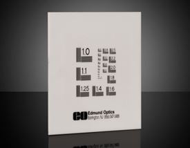
NBS 1963A Resolution Target
| Volume Pricing | |
|---|---|
| Qty 1-4 | €199,82 each |
| Qty 5+ | €190,55 each |
| Need More? | Request Quote |
NBS 1963A Resolution Targets utilize the National Bureau of Standards 1963A Resolution Pattern. The slides are ideal for precision optical testing. These slides have a frequency range from 1-512 cycles/mm. NBS 1963A Resolution Target slides are available in either positive (black pattern, clear field) or negative (clear pattern, black field). Each slide is boxed.


or view regional numbers
QUOTE TOOL
enter stock numbers to begin
Copyright 2025 | Edmund Optics BV, De Maas 22B, 5684 PL Best, The Netherlands
California Consumer Privacy Acts (CCPA): Do Not Sell or Share My Personal Information
California Transparency in Supply Chains Act
The FUTURE Depends On Optics®