
 TECHSPEC® components are designed, specified, or manufactured by Edmund Optics. Learn More
| Volume Pricing | |
|---|---|
| Qty 1-5 | €40,69 each |
| Qty 6-25 | €32,45 each |
| Qty 26-49 | €30,39 each |
| Need More? | Request Quote |
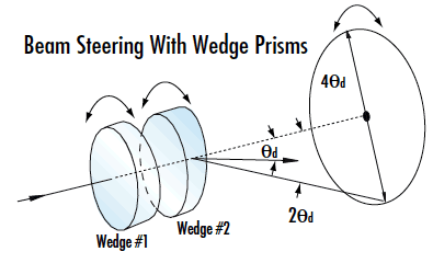
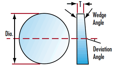
Wedge prisms can be used individually to deviate a laser beam a set angle, or two wedge prisms can be used together for beam steering applications. A single wedge prism's ability to deviate the angle of an incident beam is measured in Diopters with 1 diopter deviating the beam 1cm at a 1m working distance.
Two wedge prisms can be used as an anamorphic pair for beam shaping (to correct the elliptical shape of diode outputs). Wedge prisms can also be paired to steer a beam anywhere within a circle described by the full angle 4θ, where θ is the deviation from a single prism. This beam steering is accomplished by rotating the two wedge prisms independently of each other and is typically used to scan a beam to different locations in imaging applications.
Note: Beam deviation is shown in degrees and diopters. One diopter is 1cm of deviation at a distance of 1m from the prism.
| N-BK7 | |
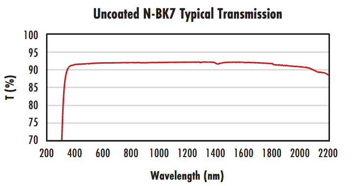 |
Typical transmission of a 3mm thick, uncoated N-BK7 window across the UV - NIR spectra. |
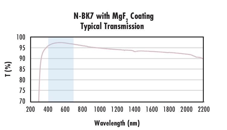 |
Typical transmission of a 3mm thick N-BK7 window with MgF2 (400-700nm) coating at 0° AOI. The blue shaded region indicates the coating design wavelengh range, with the following specification: Ravg ≤ 1.75% @ 400 - 700nm (N-BK7) Data outside this range is not guaranteed and is for reference only. |
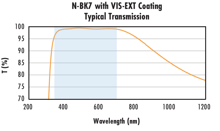 |
Typical transmission of a 3mm thick N-BK7 window with VIS-EXT (350-700nm) coating at 0° AOI. The blue shaded region indicates the coating design wavelengh range, with the following specification: Ravg ≤ 0.5% @ 350 - 700nm Data outside this range is not guaranteed and is for reference only. |
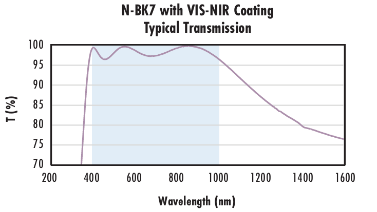 |
Typical transmission of a 3mm thick N-BK7 window with VIS-NIR (400-1000nm) coating at 0° AOI. The blue shaded region indicates the coating design wavelengh range, with the following specification: Rabs ≤ 0.25% @ 880nm Data outside this range is not guaranteed and is for reference only. |
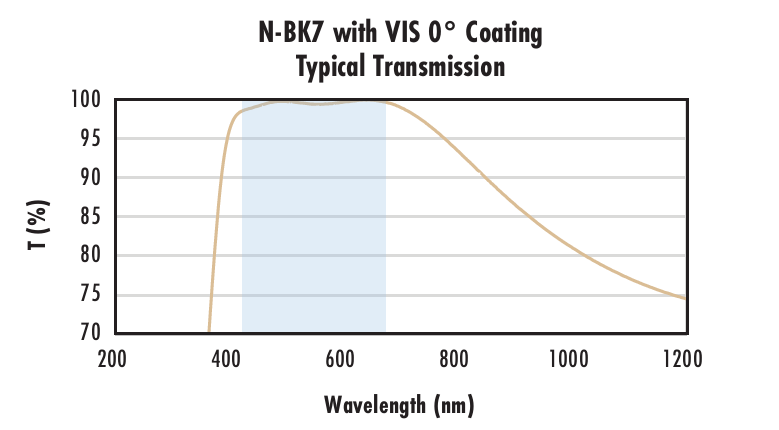 |
Typical transmission of a 3mm thick N-BK7 window with VIS 0° (425-675nm) coating at 0° AOI. The blue shaded region indicates the coating design wavelengh range, with the following specification: Ravg ≤ 0.4% @ 425 - 675nm Data outside this range is not guaranteed and is for reference only. |
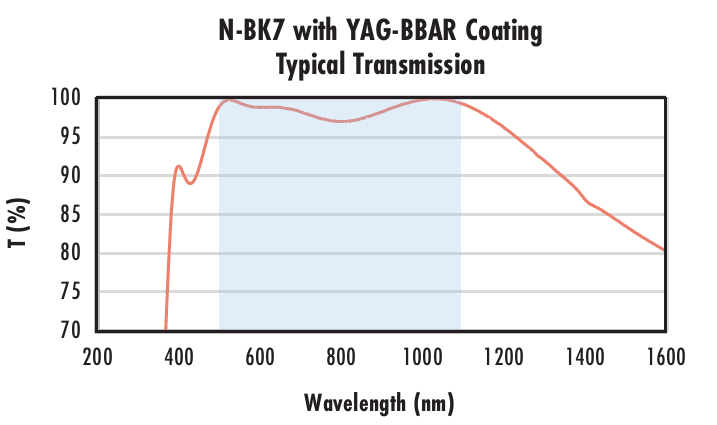 |
Typical transmission of a 3mm thick N-BK7 window with YAG-BBAR (500-1100nm) coating at 0° AOI. The blue shaded region indicates the coating design wavelengh range, with the following specification: Rabs ≤ 0.25% @ 532nm Data outside this range is not guaranteed and is for reference only. |
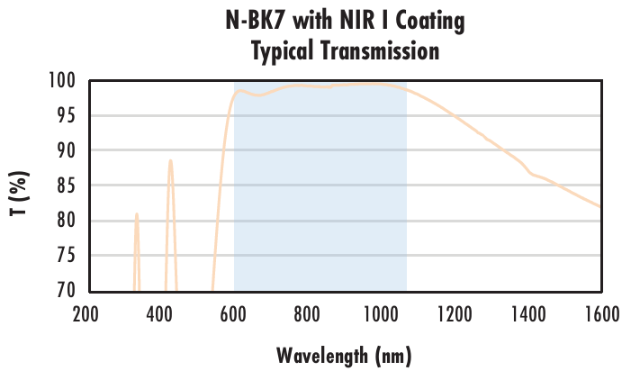 |
Typical transmission of a 3mm thick N-BK7 window with NIR I (600 - 1050nm) coating at 0° AOI. The blue shaded region indicates the coating design wavelengh range, with the following specification: Ravg ≤ 0.5% @ 600 - 1050nm Data outside this range is not guaranteed and is for reference only. |
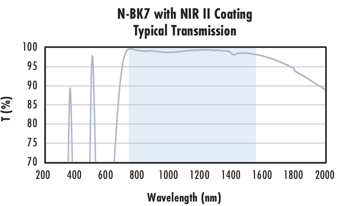 |
Typical transmission of a 3mm thick N-BK7 window with NIR II (750 - 1550nm) coating at 0° AOI. The blue shaded region indicates the coating design wavelengh range, with the following specification: Rabs ≤ 1.5% @ 750 - 800nm Data outside this range is not guaranteed and is for reference only. |
Edmund Optics offers comprehensive custom manufacturing services for optical and imaging components tailored to your specific application requirements. Whether in the prototyping phase or preparing for full-scale production, we provide flexible solutions to meet your needs. Our experienced engineers are here to assist—from concept to completion.
Our capabilities include:
Learn more about our custom manufacturing capabilities or submit an inquiry here.
or view regional numbers
QUOTE TOOL
enter stock numbers to begin
Copyright 2025 | Edmund Optics BV, De Maas 22B, 5684 PL Best, The Netherlands
California Consumer Privacy Acts (CCPA): Do Not Sell or Share My Personal Information
California Transparency in Supply Chains Act
The FUTURE Depends On Optics®